How to Adjust parameters for different plastic welding materials is not a matter of turning one control upward. Each polymer reacts differently to heat, pressure, vibration, and cooling speed. Polyethylene may need broader thermal tolerance, while polypropylene can punish poor surface preparation. PVC may degrade when exposed to excessive heat. PA materials can also absorb moisture before welding, creating bubbles, weak seams, or visible whitening.
The industry scale makes this issue difficult to ignore. PlasticsEurope reported approximately 400.3 million tonnes of global plastics production in 2022. Meanwhile, ISO 21307 provides standardized guidance for polyethylene pipe butt fusion, including heating, joining, and cooling stages. These figures and standards show a practical truth: material-specific settings support repeatable production, not merely attractive welds.
Dr. David Grewell, a recognized specialist in plastics joining and ultrasonic welding, offers a useful principle: “Good welding starts with understanding the material, not guessing at the machine settings.” The wording is simple. The factory floor is not. A clean PP sheet may weld smoothly at one energy level, while a reinforced grade may require a different amplitude, hold time, or clamping force. Small changes matter.
This guide examines temperature, pressure, energy, speed, and cooling time for common plastic welding materials. It also considers moisture, additives, thickness, joint design, and equipment condition. Some recommendations remain approximate. That is intentional. Real production lines contain variation, and a parameter chart cannot replace trial welds, visual inspection, and destructive testing. Reliable adjustment begins with measurement, then improves through disciplined reflection.
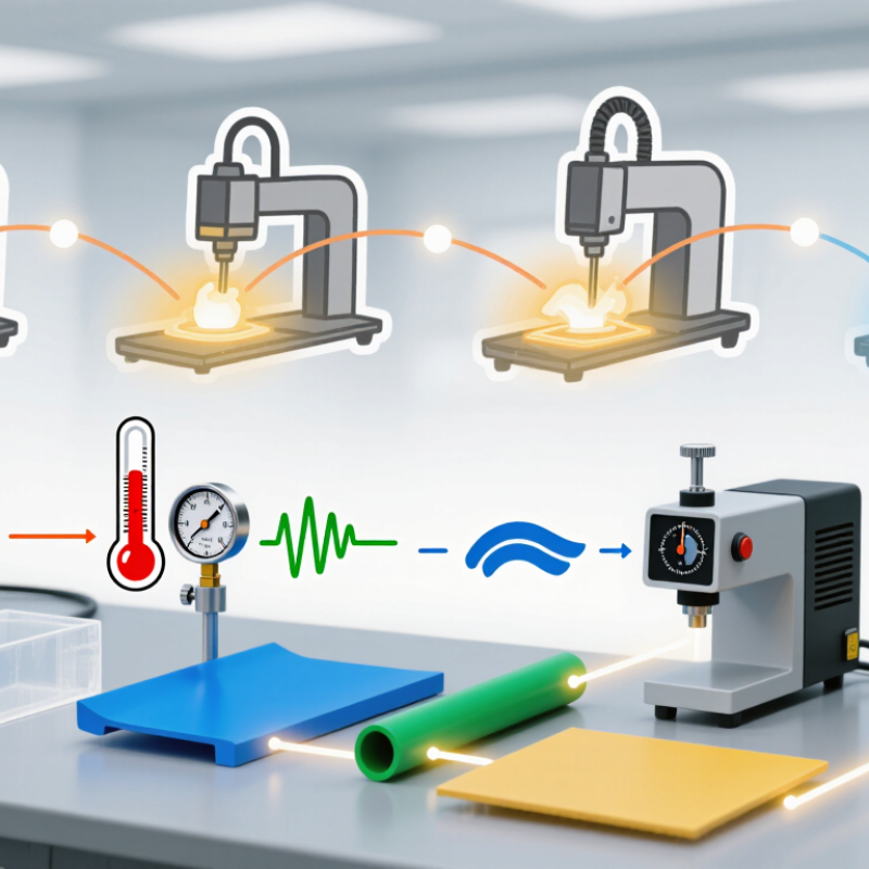
How to Adjust Plastic Welding Settings for Each Material?
Identify the Plastic Material and Its Welding Characteristics
Before changing pressure or heat, identify the resin. Look for a molded material code, part drawing, or supplier specification. A recycling symbol can help, but it does not prove the exact grade or additives. PlasticsEurope’s Plastics—The Fast Facts 2023 reports 400.3 million tonnes of global plastics production in 2022. That scale reflects a wide range of formulations, not one universal welding recipe.
Check whether the plastic is semi-crystalline or amorphous. Polyethylene and polypropylene soften across a melting range; ABS softens gradually instead. Their response to heat differs. A shiny, stringy bead may indicate excess heat, while a weak seam can point to poor contact, contamination, or insufficient energy. These clues are useful, but not conclusive. I would verify them with a small trial weld.
Record the grade, color, filler content, and moisture condition, then consult the resin supplier’s processing data. ISO 1133-1 describes measuring melt mass-flow rate, a useful way to compare material flow under specified conditions. It is not a welding-setting chart. Start with conservative settings, change one variable at a time, and inspect a cut cross-section for voids or an uneven bond. Small details matter. A filled grade may need a different approach from an unfilled one, even when both carry the same polymer code.
Identify the plastic material and its welding characteristics before setting the tool. The chart shows indicative hot-air welding temperature ranges; actual settings depend on the equipment, filler rod, material thickness, and technique.
Use the same polymer for the base material and filler rod, and adjust settings through test welds. Follow material and equipment guidance; provide suitable ventilation, especially when welding PVC.
How to Adjust Plastic Welding Settings for Each Material?
Choose a Welding Method Suitable for the Polymer
Plastic welding begins with polymer behavior, not machine settings. Check whether the parts are thermoplastic and chemically compatible. Polyethylene and polypropylene often suit hot plate or extrusion welding. Their low surface energy can still cause weak bonding if surfaces are dirty or oxidized. Clean the joint, remove damaged edges, and use a small test coupon.
Ultrasonic welding works well with rigid parts, especially when the joint includes an energy director. It may perform poorly on soft polyethylene or flexible thermoplastic elastomers. Vibration welding suits larger components and can tolerate slight surface variation. Hot gas welding remains practical for plastic sheets and repairs, but heat control requires patience. Excessive heat creates a glossy, collapsed edge.
Semi-crystalline polymers need careful control because their melting range differs from amorphous plastics. Polyamide may require drying before welding because absorbed moisture can create bubbles. Acrylonitrile butadiene styrene usually responds well to controlled hot air or ultrasonic energy. Polycarbonate can suffer from stress cracking when pressure or temperature is excessive. Reduce one variable at a time. Track temperature, travel speed, force, and cooling time. I still find that published settings are starting points, not promises. A joint can look clean and remain weak. Cut a sample cross-section, inspect the fusion line, and test it under realistic load. My first adjustment is often too aggressive. That mistake is useful when the notes are honest.
The values below are practical starting ranges, not universal specifications. Actual settings depend on part geometry, joint design, equipment, material grade, and additives. Verify settings with the resin supplier’s guidance and test welds before production.
| Polymer | Suitable Welding Method | Typical Starting Settings | Material-Specific Considerations | Useful Weld Check |
|---|---|---|---|---|
| Polypropylene (PP) | Hot-plate or hot-gas welding | Hot plate: approximately 200–240°C. Hot gas: begin around 300–350°C at the nozzle and adjust to the material and airflow. | Use compatible PP parts and filler rod. Keep surfaces clean and dry. Excessive heat can cause degradation or a weak, discolored joint. | Look for a continuous bead or uniform melt collapse without scorching, voids, or excessive flash. |
| High-density polyethylene (HDPE) | Hot-plate, butt-fusion, or hot-gas welding | Hot plate or fusion interface: commonly around 200–230°C. Follow the applicable pipe or equipment procedure for pressure and cooling time. | Match the resin type and melt-flow characteristics where possible. For pipe fusion, use a qualified procedure rather than a temperature-only setting. | Check for an even bead around the joint and consistent alignment; inspect pipe welds using the relevant procedure or standard. |
| Acrylonitrile butadiene styrene (ABS) | Hot-plate or hot-gas welding | Hot plate: approximately 220–260°C. For hot gas, start within the equipment and filler-rod supplier’s recommended range, often roughly 300–350°C at the nozzle. | Use ABS-compatible filler. Avoid prolonged heating, which can cause bubbling, discoloration, or material breakdown. | Check for a smooth, continuous joint with no bubbles, burnt areas, or gaps. |
| Polycarbonate (PC) | Hot-plate or ultrasonic welding | Hot plate: approximately 260–300°C. For ultrasonic welding, establish amplitude, pressure, and weld time through controlled trials; settings are equipment- and joint-specific. | Drying may be necessary if the grade has absorbed moisture. Avoid excessive heat or ultrasonic energy, which can cause haze, cracking, or stress marks. | Inspect for cracks, whitening, bubbles, and consistent joint strength across test samples. |
| Polyamide (PA, nylon) | Hot-plate or ultrasonic welding | Hot-plate temperatures are grade-dependent; many processes use roughly 220–280°C. Set ultrasonic amplitude, pressure, and time by trials for the specific grade and joint. | Moisture strongly affects processing. Condition or dry material as specified for the grade, and account for glass-fiber reinforcement if present. | Check for uniform joining, minimal flash, and no brittle fracture; compare conditioned samples when moisture is relevant. |
| Polyvinyl chloride (PVC) | Hot-gas welding | Use a controlled hot-gas temperature suitable for the PVC grade and filler rod; a common trial range is approximately 250–350°C at the nozzle. | PVC is sensitive to overheating and can release hazardous decomposition products. Provide effective ventilation and stop if fumes or discoloration occur. | Look for a consistent bead and avoid brown or black discoloration, which can indicate overheating. |
| Polyethylene terephthalate (PET) | Hot-plate or ultrasonic welding | Hot-plate settings are grade- and process-dependent; use the resin supplier’s guidance and determine the operating window through trials. Ultrasonic settings must be tuned to the part and horn. | Moisture control is important for many PET grades. Confirm that the selected welding process is appropriate for the specific PET formulation and part design. | Check for a uniform joint and watch for bubbles, haze, or other signs of moisture-related or thermal damage. |
| Poly(methyl methacrylate) (PMMA, acrylic) | Hot-plate or laser welding with a suitable joint design | For hot-plate welding, establish temperature and contact time with the supplier’s guidance and test samples. Laser settings depend on wavelength, material transmission, and joint geometry. | PMMA can crack or craze under heat and stress. Laser welding generally requires a suitable optical arrangement, such as a transmissive part paired with an absorbing layer. | Inspect for cracks, crazing, bubbles, and optical distortion; use a strength test appropriate to the application. |
Plastic welding settings should match the material, part thickness, and joint design. Start with the resin’s recommended processing range, then adjust temperature in small increments. A surface that looks glossy or deformed may be overheating; a joint that separates cleanly may need more heat or contact time. Watch the seam, not just the display.
Pressure matters just as much. Apply enough force to bring softened surfaces together, but avoid squeezing molten plastic out of the joint. Thin sheets often need lighter pressure than thick molded parts. Keep the tool aligned, and check that the clamp applies force evenly. Small changes matter.
Set welding time to allow the interface to soften without damaging nearby areas. For thicker parts, heating may take longer, while cooling under pressure helps the joint hold its shape. Use sample pieces made from the same material and thickness before adjusting a finished part. Change one setting at a time, record the results, and inspect the seam after cooling. A narrow, even bead can be a useful sign, though it does not prove the joint is strong. That part is easy to overlook. Test the joint using a method suited to its real use, and revise the settings if results vary.
Run a test weld before committing to a full repair or production run. Use matching scrap from the same plastic grade and similar thickness whenever possible. Set the temperature, pressure, and welding speed near the material’s recommended starting range, then make a short joint. Let it cool without pulling or bending it. Keep a note of each setting; memory is unreliable when several samples look alike.
Inspect the joint in good light. Look for gaps, uneven bead width, discoloration, bubbles, or a scorched surface. These clues can point to low heat, poor contact, or excessive heat. Gently flex the sample if the application allows. A sound weld should not peel apart cleanly along the seam. That said, a strong-looking bead can hide a weak bond. One test may mislead.
Change only one setting at a time, then weld another sample. If the plastic melts away or forms a brittle edge, reduce heat or shorten exposure. If the seam separates with little effort, check alignment and contact pressure before raising temperature. Record what changed and what the joint did. Small differences matter. Material labels, pigments, and moisture can affect results, so verify the settings on actual parts before relying on them.
Plastic welding settings should follow the material, not a fixed chart. Polyethylene softens differently from polypropylene, while ABS needs tighter heat control. Start with the lowest effective temperature and moderate travel speed. Increase heat in small steps, such as 5–10°C, and watch the bead. A glossy, collapsing surface signals excess heat. A dry, cracked bead often means insufficient fusion or poor cleaning. Record nozzle temperature, pressure, speed, and cooling time after each trial. This creates a reliable reference for future work.
Material thickness also changes the setup. Thin sheets may warp under prolonged heating, so faster passes and lighter pressure can help. Thicker sections often need preheating and slower movement. For PVC, avoid overheating and stop if fumes or discoloration appear. With ABS, clean edges and steady pressure usually improve joint consistency. Polypropylene can resist bonding when surfaces are contaminated. Scrape, wipe, and fit the parts tightly. Small details matter.
Tips: Make a test coupon from the same batch and thickness. Measure the joint after cooling, not while it is soft. Check for voids, uneven width, and weak corners. Let the sample rest overnight when practical. My own settings are not always repeatable; humidity, tool calibration, and operator angle can change results. That is worth admitting. Use technical material data as a cross-check, then approve production settings through documented trials.
Check the molded material code, part drawing, or supplier specification. A recycling symbol helps, but it cannot confirm the exact grade or additives. Record the polymer type, color, filler content, and moisture condition.
Different plastics respond differently to heat and pressure. Semi-crystalline plastics soften across a melting range. Amorphous plastics soften gradually. One setting cannot suit every formulation.
Watch for a shiny, stringy bead, discoloration, bubbles, or a scorched surface. The plastic may also melt away or develop a brittle edge. Reduce heat or shorten exposure.
Make a short test weld using matching scrap. Use the same grade and similar thickness whenever possible. Let the sample cool without pulling or bending it. Small samples reveal problems early.
Begin near the recommended temperature, pressure, and speed range. Change only one setting at a time. Record every adjustment beside the sample. Memory becomes unreliable quickly.
Use strong, even lighting. Check for gaps, uneven bead width, bubbles, discoloration, and surface scorching. If suitable, gently flex the sample. A strong-looking bead may still hide a weak bond.
Check alignment, contact pressure, contamination, and insufficient energy. Do not immediately raise the temperature. Poor contact may be the real problem. That mistake is easy to make.
A cut cross-section can reveal voids or an uneven bond. Surface appearance alone is not enough. Inspect the internal joint before trusting the settings. One test can fool you.
Yes. A filled grade may need different settings from an unfilled grade. Pigments can alter heat response. Moisture may also affect the joint. Verify settings on actual parts before production.
Adjusting plastic welding settings begins with identifying the polymer and understanding its welding characteristics, including its melting range, thermal sensitivity, and compatibility with other materials. The welding method should then be selected according to the plastic type, joint design, and required strength. Key parameters such as temperature, pressure, and welding time must be balanced carefully: excessive heat may deform the material, while insufficient heat can result in weak bonding. Learning how to adjust parameters for different plastic welding materials helps create more reliable and consistent joints.
Before production, perform a test weld using the selected settings and inspect the joint for proper fusion, alignment, surface condition, and strength. Based on the results, fine-tune each parameter gradually rather than changing several settings at once. Different materials may require unique combinations of heat, force, and cooling time, so careful testing and documentation are essential for achieving stable welding quality.

Heping Mechanical