Welding molds and fixtures work under heat, pressure, vibration, and repeated clamping. In Chinese manufacturing plants, even a small alignment error can mark a part or accelerate tool wear. A fixture that looks stable may already have loosened locating pins, cracked welds, or uneven contact surfaces.
This guide examines China’s top 10 practical methods for improving tool durability and production consistency. It explains how to extend the service life of welding molds and fixtures through accurate alignment, suitable materials, controlled welding parameters, regular cleaning, and timely maintenance. Each method connects workshop experience with basic engineering principles. For example, removing spatter from a locating surface can prevent a few millimeters of positioning error during the next assembly cycle.
Small details matter.
The discussion also covers lubrication, cooling, storage, clamping force, inspection records, and fixture redesign. These actions may seem routine, but they directly affect dimensional accuracy, downtime, and replacement costs. Experienced technicians often detect problems by listening for abnormal clamp movement or checking uneven discoloration near a weld zone. However, visual inspection alone is not enough. Some internal cracks and gradual deformation require measurement tools and scheduled verification.
No single maintenance plan fits every factory. Steel grade, welding current, production volume, and working temperature change the result. This overview therefore encourages careful testing, documented observations, and honest review of failed practices. A longer tool life should never reduce operator safety or product quality.
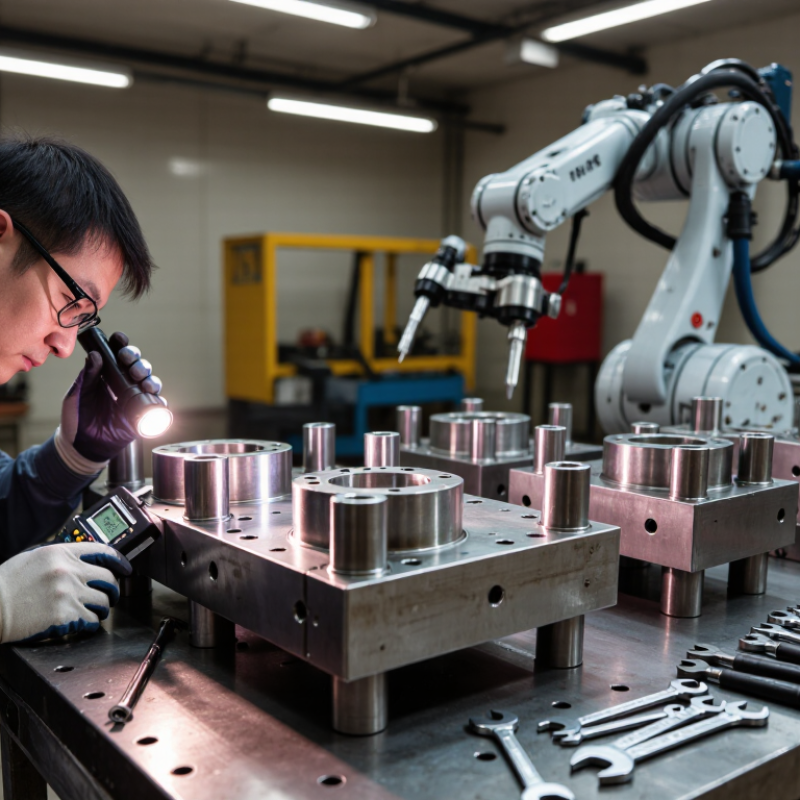
China Top 10 Ways to Extend Welding Mold Life
Extending welding mold life starts with the steel, not the repair torch. Check hardness, toughness, heat-treatment history, and corrosion condition. A hardened cavity may resist wear but crack during welding. A tougher steel may tolerate impact yet deform under high pressure. Measure it. Do not guess.
Load changes the repair decision. Record clamping force, injection pressure, cycle temperature, and ejection resistance. Inspect the damaged area under magnification. Short cracks near corners often indicate thermal fatigue. Deep grooves may come from abrasive particles or excessive sliding load. Deformation usually signals insufficient hardness, poor support, or repeated overload. The failure mode matters more than the visible mark.
Match the repair to the evidence. Minor wear may need polishing, lapping, or a controlled surface treatment. Cracks require complete removal before welding, followed by suitable preheating and gradual cooling. Use a compatible filler, and verify the heat-affected zone afterward. For heavily loaded areas, a replaceable insert may provide more reliable service than repeated weld repairs. Check dimensions after machining; excessive polishing can enlarge a cavity and change part geometry. That mistake is easy to miss. In practice, repair records should include steel data, crack location, hardness readings, and cycle history. A repair that survives ten cycles is not proven. Monitor it over time, because some failures appear only after thermal cycling.
China Top 10 Ways to Extend Welding Mold Life: Match H13 Filler Metal to a 44–52 HRC Mold Working Hardness
H13 mold steel performs best when the repair filler matches its working hardness, not merely its color or welding ease. ASM Handbook, Volume 4, reports that heat-treated H13 commonly operates around 44–52 HRC, depending on tempering conditions. Select H13-compatible filler metal within that hardness range after heat treatment. A softer deposit may deform under repeated impact. An excessively hard deposit can crack beside the weld.
Measure the original mold with a calibrated Rockwell tester before welding. ASTM E18 defines the Rockwell hardness testing method, including surface preparation and load control. Record several points around the cavity, not only one convenient location. I have seen repairs fail because the operator tested clean base metal but ignored a softened heat-affected zone. Small details matter.
Preheat the mold gradually, often near 300–350°C, according to its size and welding procedure. Keep interpass temperature stable, and use short beads with controlled heat input. ASM Handbook welding guidance emphasizes reducing thermal gradients in tool-steel repairs. After welding, temper the deposit and surrounding zone as the procedure requires. Then retest hardness. A 44–52 HRC target sounds precise, but real molds may show uneven hardness after years of thermal cycling. The repair plan should allow for that imperfection.
This practical priority ranking highlights the main controls used to extend H13 mold life during welding repair. Matching the filler metal and final deposit to a working hardness of 44–52 HRC is central, while controlled preheating, low-hydrogen practice, gradual cooling, tempering, and final inspection help reduce cracking, distortion, and premature wear. The scores indicate relative engineering priority, not guaranteed percentage life extension.
Mold repair welding begins with temperature control, not filler selection. Preheat the entire repair zone evenly between 250 and 350°C. Avoid heating only the damaged edge. That creates steep thermal gradients and can promote cracking.
Use contact thermocouples or temperature crayons at several points around the cavity. An infrared gun alone may misread polished or oxidized surfaces. Keep the mold covered during heating, especially in a cold workshop. A slow, uniform rise helps reduce thermal shock and hydrogen-related defects. Small molds may heat quickly, but large blocks often need much longer.
Measure interpass temperature before every new bead. Keep it below 350°C, even when production pressure is high. Excessive heat can soften the heat-affected zone, change hardness, and distort the cavity. Let the mold cool naturally when necessary. Do not use water or a strong air blast unless the qualified welding procedure allows it.
Shop experience shows that temperature records improve repeatability. Record the starting temperature, peak preheat, interpass readings, and cooling time. We sometimes trust a single reading too much; that is a weakness worth correcting. After welding, inspect hardness and dimensions before machining. Material grade, section thickness, and repair depth still require procedure-specific confirmation.
Low-hydrogen welding electrodes can help extend mold life by reducing cold-crack risks around repaired cavities, corners, and hardened sections. Bake them at 300–350°C only when the electrode classification permits this range. ISO 3690:2018 measures diffusible hydrogen in milliliters per 100 grams of deposited weld metal. Its H5 level is no more than 5 mL/100 g under controlled testing. Lower hydrogen is valuable, but it cannot compensate for dirty steel or poor preheating.
A practical workshop routine matters. Place unopened electrodes in a calibrated oven, complete the approved holding cycle, and transfer them into a heated portable container. Do not leave them beside a damp welding table. Moisture can return quickly. The International Institute of Welding links hydrogen control with lower cold-cracking risk, especially when restraint and hardenable steels are present. Clean oil, scale, and rust from the mold before welding. Maintain the specified interpass temperature, and use short, controlled arcs.
The process is not foolproof. Repeated baking can damage some coatings, so the electrode data sheet and applicable welding procedure must govern. Record oven temperature, exposure time, and container temperature. That small log often reveals hidden failures. In my experience, many mold cracks begin with neglected storage rather than dramatic welding mistakes. A 300–350°C bake is useful, but only as one part of a disciplined repair system. Preheat verification still deserves more attention.
| No. | Life-Extension Method | Recommended Practice | Control Point or Typical Target | How It Protects the Mold |
|---|---|---|---|---|
| 1 | Use Low-Hydrogen Electrodes | Use properly classified low-hydrogen electrodes for the mold steel and welding position. Bake electrodes at 300–350°C when required by the electrode specification, then keep them in a controlled holding oven. | Typical holding temperature: approximately 100–150°C after baking; use only within the specified exposure time. | Reduces diffusible hydrogen, lowering the risk of delayed hydrogen cracking, underbead cracking, and premature repair failure. |
| 2 | Preheat the Mold Uniformly | Preheat the repair area and surrounding section before welding. Use temperature crayons, contact thermometers, or calibrated infrared instruments to verify temperature at several locations. | Common repair ranges are about 150–300°C, depending on steel chemistry, section thickness, restraint, and consumable requirements. | Slows cooling, reduces thermal gradients, and decreases the formation of hard, crack-sensitive microstructures. |
| 3 | Control Interpass Temperature | Measure interpass temperature before depositing the next bead. Do not allow the mold to become excessively cold or overheated during multi-pass welding. | Keep the interpass range within the qualified welding procedure; many tool-steel repairs use approximately 150–300°C. | Maintains consistent metallurgical conditions and helps prevent both hydrogen cracking and excessive softening of the heat-affected zone. |
| 4 | Remove Oil, Rust, and Moisture | Degrease the repair zone and remove rust, paint, scale, coolant residue, and moisture. Dry the joint immediately before welding. | The surface should be visibly clean, dry, and free from contaminants that can introduce hydrogen or inclusions. | Prevents porosity, slag entrapment, lack of fusion, and hydrogen pickup at the repair interface. |
| 5 | Prepare a Sound Repair Cavity | Remove all cracked or overheated material by machining, grinding, or controlled gouging. Use crack-detection methods where necessary to confirm complete removal. | The cavity should have rounded transitions, clean sidewalls, and no sharp corners or remaining crack tips. | Eliminates stress concentrators and provides sufficient access for full fusion and proper bead placement. |
| 6 | Apply Short, Balanced Weld Beads | Deposit short beads with a controlled sequence, alternating sides or directions where practical. Clean slag between passes and avoid excessive weaving. | Use the qualified current, voltage, travel speed, and bead size; keep heat input consistent throughout the repair. | Limits distortion, residual stress, localized overheating, and uneven hardness in the repaired mold area. |
| 7 | Use the Correct Filler Metal | Select filler metal compatible with the base steel, required hardness, wear resistance, toughness, and subsequent machining process. | Verify chemical compatibility, weldability, hardness after treatment, and any required tempering or stress-relief procedure. | Reduces mismatch in hardness and thermal expansion, improving resistance to cracking, chipping, and wear during service. |
| 8 | Cool Slowly After Welding | After welding, maintain the specified temperature and allow the mold to cool gradually under insulation or in a controlled furnace when required. | Avoid forced-air or water cooling; the cooling procedure should follow the qualified welding and heat-treatment procedure. | Reduces residual stress and prevents sudden transformation or thermal shock in the weld and heat-affected zone. |
| 9 | Stress-Relieve and Temper When Required | Apply post-weld heat treatment when required by the steel grade, repair depth, restraint level, or service condition. Match the treatment to the original mold heat treatment whenever possible. | Use a documented furnace cycle with controlled heating, soaking, and cooling; avoid temperatures that reduce required mold hardness. | Relieves residual welding stress and stabilizes the repaired structure, reducing distortion and delayed cracking. |
| 10 | Inspect and Maintain the Repair | Perform visual inspection and, where appropriate, dye penetrant, magnetic-particle, ultrasonic, or hardness testing. Monitor the mold during service and repair small defects early. | Record welding parameters, electrode exposure, preheat, interpass temperature, inspection results, and repair locations. | Detects defects before they grow into major failures and creates a repeatable maintenance history for future repairs. |
Long mold life starts before the first arc.
Clean the joint, confirm fit-up, and preheat according to the steel specification. Use compatible filler metal and keep interpass temperature within the welding procedure. Protect the mold from arc strikes, sharp starts, and sudden temperature changes. Small errors accumulate. After welding, stress relief at 550–600°C can reduce residual stress and distortion. Use calibrated thermocouples, record the soak temperature, and control holding time for section thickness. Never assume one schedule suits every mold. That shortcut often causes trouble.
Cool the mold gradually inside the furnace or under controlled insulation. Do not quench it in air or water. Rapid cooling can reopen cracks near repaired corners. Once the mold reaches a safe inspection temperature, perform visual checks and suitable NDT. Magnetic particle testing can reveal surface-breaking flaws in ferromagnetic steel. Ultrasonic testing can examine deeper areas. Liquid penetrant testing helps inspect nonmagnetic surfaces. Record each indication with its location, size, and photographs. Cleanliness matters.
Schedule inspections after defined production cycles, not only after failure. Check vents, parting lines, cooling channels, hardness, and repaired zones. Remove buildup carefully, lubricate moving parts, and correct minor damage before it spreads. Compare every report with earlier measurements. A practical log exposes patterns. I have seen teams extend mold life by improving records and cooling discipline. Still, inspection intervals should change when loads, alloys, or cycle times change. Maintenance plans need revision.
Aim for 44–52 HRC after heat treatment. The correct target depends on the mold’s tempering history. This range is useful, not magical. Uneven hardness can remain after years of cycling.
A softer weld deposit may deform under repeated impact. An excessively hard deposit can crack beside the repaired area. Match the filler to the working hardness, not its color or easy handling.
Use a calibrated Rockwell tester. Measure several points around the cavity, corners, and repaired zone. Prepare the surface carefully. One reading is not enough.
The heat-affected zone may soften during earlier repairs or production. Testing only clean base metal can hide this weakness. That mistake is easy to make.
Preheat the mold gradually, often near 300–350°C. Follow the approved welding procedure for the mold size. Use short beads and control heat input. Keep the interpass temperature stable.
Temper the weld deposit and nearby zone as required. Then retest hardness at several locations. The numbers may disagree slightly. That deserves investigation, not immediate acceptance.
Stress relief around 550–600°C can reduce residual stress and distortion. Use calibrated thermocouples and record the soaking temperature. Holding time should reflect the mold section thickness. One schedule cannot suit every mold.
Cool it gradually inside a furnace or controlled insulation. Do not quench it with air or water. Rapid cooling may reopen cracks near repaired corners. After cooling, use visual checks and suitable nondestructive testing.
Inspect the mold after defined production cycles, not only after failure. Check vents, parting lines, cooling channels, hardness, and repaired areas. Record locations, measurements, and photographs. Review the plan when loads or cycle times change.
How to extend the service life of welding molds and fixtures begins with a careful assessment of the mold steel, operating load, damage pattern, and likely failure mode. This evaluation helps determine whether welding repair is appropriate and guides the selection of compatible repair materials. For molds with a working hardness of approximately 44–52 HRC, H13-type filler metal can provide a suitable balance of hardness, toughness, and thermal resistance when properly applied.
Reliable results also depend on strict welding temperature control. Preheat the mold to 250–350°C and keep the interpass temperature below 350°C to reduce thermal stress and cracking. Use a low-hydrogen welding process, with electrodes baked at 300–350°C and protected from moisture. After welding, complete machining and apply stress relief at 550–600°C, followed by suitable non-destructive testing, controlled cooling, and dimensional inspection. Regular cleaning, lubrication, load monitoring, and scheduled maintenance can further prevent repeated damage and extend service life.

Heping Mechanical